Schematic Elements for Guitar and Effects: Opamp Stages, Boosts, and the MXR MicroAmp
6.9K views · Aug 29, 2022 · Music

Comments · 23
@MrBlockHead · 1 year ago
This video was helpful. I’ve learned a lot about op amp circuits but didn’t quite understand about the caps in op ap gain section. You earned a sub
2
@Blaculo · 3 years ago
Awesome explanations. Thank you.
1
@paatyki · 1 year ago (edited)
Hi, I found your channel totally by accident and I decided to sub it 'cause you talk about things that interest me in a very accessible way. Thank you very much for that. <br>But to the point. <br>When describing the elements of the non-inverting op amp stage, you did not mention another important role played by the C3 capacitor in this topology.<br>In addition to limiting the bandwidth from the bottom, it divides the negative feedback loops separately for DC and AC signals. <br>Why is it so important?<br>Op amps are not ideal components. Small imperfections like few mV offset voltage at the input multiplied by a very high gain of circuits like overdrive, or booster can cause a large constant voltage at the output, which interferes with the operation of other elements, for example clipping diodes . This is why we use C3 cap at feedback loop. So for AC signals, as you explained in the movie, the gain is determined by the ratio of impedance (R4 C2 ) to (R5 R6 C3) and can be very high, while for unwanted DC signals, the feedback loop is closed only by the resistor R4, which means that the gain is only 1.
2
@SoundSeeker2024 · 3 months ago
Excellent! Thanks!
@rogerw4024 · 1 year ago
Great explanation, like why the resistor is so high to bias the op amp, after watching this video im starting to get a better grasp on these simple circuits. Appreciate you sharing your knowledge and time!!!
@satselab · 1 year ago
Great video and precise explanations!
@cdecdecdecdecde · 3 years ago
Really good walkthrough, thanks dude!
@patrikdunmar8022 · 1 year ago
❤
@66Gollum · 1 year ago
Thank you again, this was very clear - but why is R5 soo big, as far as I understand it will reduce the output If pulled up?
@Pentode3000 · 2 years ago
R9 is NOT to be omitted!!! It decouples the TL072 from capacative loads like a long guitar cable. The TL series has a tendency to oscillate with capacitive loads. I would suggest a minimum of 100 Ohms. Overall good explanations but you should pay more attention to those RC Filter relations. Making C1 bigger will absolutely do nothing for the bass response if you leave R2 and R1 the way they are. On the other hand you will cut bass if you put 100n in for C5 and leave R10 as 10k.
7
@Get.Wired.Studios · 4 years ago
Just an edit, your gain pot lugs 1 and 2 should be connected together rather than 2 and 3. The way you have yours wired, turned the pot all the way down (counterclockwise) would be maximum gain and turning it all the way up would be minimum gain.
2
@dmilotte · 3 years ago
Great info, do you build this pedal in another video?
Up next

Schematic Elements for Guitar and Effects: Soft Clipping, Overdrive, the Blues Breaker and TS-808
TheScientificGuitarist · 6.2K views

Schematic Elements for Guitar and Effects: BBD's and the Boss CE-2
TheScientificGuitarist · 3.6K views

Designing Dirt Pedals - Understanding Op-amp Distortion and Overdrive
CalSonics · 35K views

Schematic Elements for Guitar and Effects: Hard Clipping, Distortion, the Electra and the Rat
TheScientificGuitarist · 4.6K views

Op Amps: Bass and Treble EQ
Electronics with Professor Fiore · 12K views

Building a Clean Boost Guitar Pedal
Music Techknowledgy · 49K views

Schematic Elements for Guitar and Effects: Differential Amplifiers and the Boss BD-2
TheScientificGuitarist · 2.7K views

ECE4448 L43: Diode-Based Overdrive and Distortion Effects (Guitar Amplification and Effects)
Lantertronics · 227K views

EEVBlog 1436 - The TOP 5 Jellybean OPAMP's
EEVblog · 151K views

Op Amp Theory and Design - Phil's Lab #53
Phil’s Lab · 55K views

Op Amps: Single Supply Biasing
Electronics with Professor Fiore · 22K views

Schematic Elements for Guitar and Effects: Resonant LC Circuits and the Vox Wah
TheScientificGuitarist · 2.5K views

1970's Op-Amp Distortion (Boss DS-1, ProCo Rat, Ross Distortion, Ibanez SD-9, MXR Micro Amp)
JHS Pedals · 473K views

Fender CEO Tells Mary Spender Why He's SUING My Friends
Tim Pierce Guitar · 371K views

What do all the parts do on a guitar pedal? Zendrive circuit experiment
Wampler Pedals · 113K views

Rat Distortion Schematic Analysis
The Andromeda Corporation · 19K views

Schematic Elements for Guitar and Effects: Mu-Amps and the BSIAB
TheScientificGuitarist · 2K views

10 Opamps: DC Bias For Single Supply Circuits
trevortjes / The Repair Café · 52K views

Schematic Elements for Guitar and Effects: Tube Triode Stages and the Valvecaster
TheScientificGuitarist · 1.6K views

Schematic Elements for Guitar and Effects: LFO, PT2399, and the Little Angel Chorus
TheScientificGuitarist · 11K views
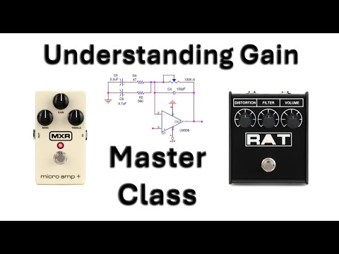
Designing Dirt Pedals - Understanding Op-amp Gain in the MXR Micro Amp and ProCo RAT
CalSonics · 10K views

A bigger, bolder, and muffier Big Muff Pi OpAmp Fuzz?
Wampler Pedals · 106K views

Improving a Clean Boost Guitar Pedal
Music Techknowledgy · 8.1K views

What no one tells you about Guitar Pedals & "clone" circuits
Wampler Pedals · 195K views

5 Kinds of Buffers in Your Guitar Pedals
DIY Guitar Pedals · 26K views

Fender 5F1 Champ Schematic - Analysis and Breakdown
Kley De Jong · 37K views